SigOS: Hardware: Difference between revisions
| Line 36: | Line 36: | ||
File:WS281 Backside Closeup.jpg|Closeup of wiring side of WS281 LED. | File:WS281 Backside Closeup.jpg|Closeup of wiring side of WS281 LED. | ||
File:WS281 Backside 2.jpg|Backside wiring of WS281 LED showing power and signal in on the left and daisy chaining to next LED on the right. | File:WS281 Backside 2.jpg|Backside wiring of WS281 LED showing power and signal in on the left and daisy chaining to next LED on the right. | ||
File:SigOS Test Box.jpg|Prototype test box shows how multiple WS281 LEDs can be daisy chained together. In this case there are 3 signal heads, each with 3 LEDs. | |||
</gallery> | </gallery> | ||
Revision as of 18:42, 5 December 2024
The Signal Operating System is designed to operate on low-cost hardware. This encourages extensive use for Signals and Detectors throughout most railroads, large and small.
Components
Control Board
Ribbon Cable

It is not necessary to use ribbon cable for wiring the hardware. However, it is low cost, convenient to work with, helps reduce "rats nest", and consistently using the same color wire for components simplifies construction and debugging.
- Wire gauge: 22, 24, or 26 AWG
- Source: Amazon.com
CdS photoresistor

A CdS photoresistor is a light-sensitive resistor. It detects the ambient light at the signal head, which SigOS uses to control the brightness of the WS281 LEDs.
- Pin 1
- Either wire from CdS photoresistor
- Wire color: Green
- Function: Variable voltage into GPIO P1 of Control Board A/D converter, voltage is inversely proportional to ambient light level
- Pin 2
- Other wire from CdS photoresistor
- Wire color: Yellow
- Function: +3.3 volt power
- Part number: GL5516
- Characteristics: Bright light 5-10k Ohms, dark 0.2M Ohms
- Source: Amazon.com
WS281 LED
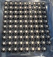
Frontside view of a sheet of WS281 LEDs.
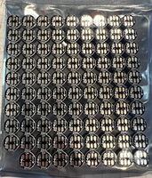
Backside view of a sheet of WS281 LEDs.
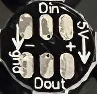
Closeup of wiring side of WS281 LED.
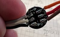
Backside wiring of WS281 LED showing power and signal in on the left and daisy chaining to next LED on the right.
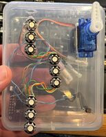
Prototype test box shows how multiple WS281 LEDs can be daisy chained together. In this case there are 3 signal heads, each with 3 LEDs.


- Description: WS2812b LED, MIT
- Pin +5V In
- Input +5 volts to power this LED and all downstram LEDs on the chain
- Pin GND In
- Ground return for +5 volts and signal
- Pin DIn
- Data Input signal, controls function of the LED
- Pin +5v Out
- Output +5 volts to power downstream LEDs in the chain
- Pin GND Out
- Output ground return for +5 volts and signal for downstream LEDs
- Pin DOut
- Output data signal, controls function of downstream LEDs
- Source: Amazon.com