SigOS: Hardware: Difference between revisions
| (22 intermediate revisions by the same user not shown) | |||
| Line 5: | Line 5: | ||
=== Control Board === | === Control Board === | ||
==== ESP32-S2 Mini ==== | |||
SigOS is currently running on an ESP32-S2 Mini board. This powerful board contains 4Mbytes of Flash and provides WiFi network connectively, plus a plethora of input output signals. | |||
<gallery widths=200px heights=200px perrow=2> | |||
File:ESP32-S2 Mini Front.jpg|Front side of ESP32-S2 Mini control board. | |||
File:ESP32-S2 Mini Back.jpg|Back side of ESP32-S2 Mini control board. | |||
File:ESP32 S2 Mini - Amazon.jpg|Pin diagram from back side of ESP32 S2 Mini control board. | |||
File:Screenshot 2024-12-12 090529.png|Wiring diagram for SigOS controller ESP32-S2 Mini. | |||
</gallery> | |||
* Pin GPIO P1 | |||
** Wire color: Green (to CdS photoresistor) | |||
** Function: Variable voltage from CdS light level sensor into Analog to Digital (A/D) converter | |||
* Pin GND | |||
** Wire color: Black to WS281 LED | |||
** Wire color: Brown to R/C servo | |||
** Function: Ground return for power and signals | |||
* Pin EN | |||
** Function: Device Enable, must be pulled high to +3.3 volts with 47K Ohm resistor | |||
* Pin 2 | |||
** Wire color: White | |||
** Function: WS281 control signal to LEDs | |||
* Pin 5 | |||
** Wire color: Orange to semaphore R/C servo | |||
** Function: PWM signal to semaphore R/C servo | |||
* Pin VBUS | |||
** Wire Color: Grey to WS281 LED | |||
** Wire Color: Red to R/C servo | |||
** Function: +5 volts power | |||
* Source: [https://www.amazon.com/DiGiYes-ESP32-S2FN4R2-ESP32-S2-Connect-MicroPython/dp/B0BXX6R15D/?_encoding=UTF8&pd_rd_w=kVBdK&content-id=amzn1.sym.255b3518-6e7f-495c-8611-30a58648072e%3Aamzn1.symc.a68f4ca3-28dc-4388-a2cf-24672c480d8f&pf_rd_p=255b3518-6e7f-495c-8611-30a58648072e&pf_rd_r=AXGXK9QGV7RFVZHTK4Y7&pd_rd_wg=t24Yd&pd_rd_r=9d61c38b-3d22-46ca-8c59-4ec700e66c10&ref_=pd_hp_d_atf_ci_mcx_mr_ca_hp_atf_d <i>Amazon.com</i>] | |||
'''Power supply''' | |||
"FencingNerd" on <i>reddit</i> said: There is no problem connecting a lithium polymer (LiPo) battery to VBUS. It has a low dropout (LDO) regulator, so you only need about 3.5V for it to maintain 3.3V. The regulator also smoothly degrades and the rated operating range is 2.8V to 3.6V for the ESP32-S2. So even if the battery runs down to 3.2V it's still within spec. | |||
'''Caution: Do NOT connect a battery to the 3V3 pin of the ESP32-S2 Mini, as it will damage the board.''' | |||
=== Resistors === | |||
* Resistor "R1" is 1K Ohm, 1/4 or 1/8 watt resistor | |||
** Function: Pull up board "Enable" signal to +3.3 volts | |||
* Resistor "R2" is 47K Ohm, 1/4 o 1/8 watt resistor | |||
** Function: Pull down to provide return path for CdS photoresistor | |||
=== Ribbon Cable === | === Ribbon Cable === | ||
| Line 39: | Line 85: | ||
File:WS281 Backside 2.jpg|Backside wiring of WS281 LED showing power and signal in on the left and daisy chaining to next LED on the right. | File:WS281 Backside 2.jpg|Backside wiring of WS281 LED showing power and signal in on the left and daisy chaining to next LED on the right. | ||
File:SigOS Test Box.jpg|Prototype test box shows how multiple WS281 LEDs can be daisy chained together. In this case there are 3 signal heads, each with 3 LEDs. | File:SigOS Test Box.jpg|Prototype test box shows how multiple WS281 LEDs can be daisy chained together. In this case there are 3 signal heads, each with 3 LEDs. | ||
File:WS281 Daisy Chain.jpg| Photo showing how nine WS281 LEDs are "daisy chained" together to form three signal heads with three LEDs each. | |||
</gallery> | </gallery> | ||
* Pin +5V In | * Pin +5V In | ||
** Input +5 volts to power this LED and all | ** Wire color: Grey | ||
** Function: Input +5 volts to power this LED and all downstream LEDs on the chain | |||
* Pin GND In | * Pin GND In | ||
** Ground return for +5 volts and signal | ** Wire color: Black | ||
** Function: Ground return for +5 volts and signal | |||
* Pin DIn | * Pin DIn | ||
** Data Input signal, controls function of the LED | ** Wire color: White | ||
** Function: Data Input signal, controls function of the LED | |||
* Pin +5v Out | * Pin +5v Out | ||
** Output +5 volts to power downstream LEDs in the chain | ** Wire color: Grey | ||
** Function: Output +5 volts to power downstream LEDs in the chain | |||
* Pin GND Out | * Pin GND Out | ||
** Output ground return for +5 volts and signal for downstream LEDs | ** Wire color: Black | ||
** Function: Output ground return for +5 volts and signal for downstream LEDs | |||
* Pin DOut | * Pin DOut | ||
** Output data signal, controls function of downstream LEDs | ** Wire color: White | ||
** Function: Output data signal, controls function of downstream LEDs | |||
* Power: 30 watts | |||
* Part number: ALITOVE WS2812B | * Part number: ALITOVE WS2812B | ||
* Source: [https://www.amazon.com/gp/product/B01D1FFVOA/ref=ppx_yo_dt_b_search_asin_title?ie=UTF8&psc=1 <i>Amazon.com</i>] | * Source: [https://www.amazon.com/gp/product/B01D1FFVOA/ref=ppx_yo_dt_b_search_asin_title?ie=UTF8&psc=1 <i>Amazon.com</i>] | ||
=== Servo === | |||
[[File:Miuzei MG90S Micro Servo.jpg|thumb|right|200px|The Miuzei MG90S Micro Server.]] | |||
A miniature [https://en.wikipedia.org/wiki/Servo_(radio_control) R/C servo] provides power to move the semaphore flag into its three positions. Be sure to use the higher quality Miuzei brand or equivalent, as they have metal gears. The cheaper units have plastic gears and may not last in the rugged conditions of a railroad. | |||
* Pin GND | |||
** Wire color: Black | |||
** Function: Return path for +5 volts and signal | |||
* Pin +5V | |||
** Wire color: Red | |||
** Function: +5 volts power supply | |||
* Pin Signal | |||
** Wire color: Orange | |||
** Function: Pulse Width Modulation (PWM) control signal | |||
* Part number: Miuzei MG90S 9G | |||
* Source: [https://www.amazon.com/dp/B0BWJ2CK9D?ref=ppx_yo2ov_dt_b_fed_asin_title&th=1 <i>Amazon.com</i>] | |||
Latest revision as of 10:09, 12 December 2024
The Signal Operating System is designed to operate on low-cost hardware. This encourages extensive use for Signals and Detectors throughout most railroads, large and small.
Components
Control Board
ESP32-S2 Mini
SigOS is currently running on an ESP32-S2 Mini board. This powerful board contains 4Mbytes of Flash and provides WiFi network connectively, plus a plethora of input output signals.
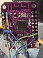
Front side of ESP32-S2 Mini control board.
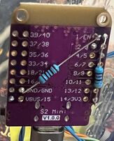
Back side of ESP32-S2 Mini control board.
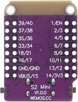
Pin diagram from back side of ESP32 S2 Mini control board.

Wiring diagram for SigOS controller ESP32-S2 Mini.


- Pin GPIO P1
- Wire color: Green (to CdS photoresistor)
- Function: Variable voltage from CdS light level sensor into Analog to Digital (A/D) converter
- Pin GND
- Wire color: Black to WS281 LED
- Wire color: Brown to R/C servo
- Function: Ground return for power and signals
- Pin EN
- Function: Device Enable, must be pulled high to +3.3 volts with 47K Ohm resistor
- Pin 2
- Wire color: White
- Function: WS281 control signal to LEDs
- Pin 5
- Wire color: Orange to semaphore R/C servo
- Function: PWM signal to semaphore R/C servo
- Pin VBUS
- Wire Color: Grey to WS281 LED
- Wire Color: Red to R/C servo
- Function: +5 volts power
- Source: Amazon.com
Power supply
"FencingNerd" on reddit said: There is no problem connecting a lithium polymer (LiPo) battery to VBUS. It has a low dropout (LDO) regulator, so you only need about 3.5V for it to maintain 3.3V. The regulator also smoothly degrades and the rated operating range is 2.8V to 3.6V for the ESP32-S2. So even if the battery runs down to 3.2V it's still within spec.
Caution: Do NOT connect a battery to the 3V3 pin of the ESP32-S2 Mini, as it will damage the board.
Resistors
- Resistor "R1" is 1K Ohm, 1/4 or 1/8 watt resistor
- Function: Pull up board "Enable" signal to +3.3 volts
- Resistor "R2" is 47K Ohm, 1/4 o 1/8 watt resistor
- Function: Pull down to provide return path for CdS photoresistor
Ribbon Cable

It is not necessary to use ribbon cable for wiring the hardware. However, it is low cost, convenient to work with, helps reduce "rats nest", and consistently using the same color wire for components simplifies construction and debugging.
- Wire gauge: 22, 24, or 26 AWG
- Source: Amazon.com
CdS photoresistor

A CdS photoresistor is a light-sensitive resistor. It detects the ambient light at the signal head, which SigOS uses to control the brightness of the WS281 LEDs.
- Pin 1
- Either wire from CdS photoresistor
- Wire color: Green
- Function: Variable voltage into GPIO P1 of Control Board A/D converter, voltage is inversely proportional to ambient light level
- Pin 2
- Other wire from CdS photoresistor
- Wire color: Yellow
- Function: +3.3 volt power
- Part number: GL5516
- Characteristics: Bright light 5-10k Ohms, dark 0.2M Ohms
- Source: Amazon.com
WS281 LED
The WS281 LED is a low-cost, high intensity, multi-color LED. It is contains its own drive and control circuitry, making it extremely easy to integrate into the SigOS project. MicroPython on the ESP32 board directly supports driving the WS281 signals. Learn more about the WS281 here: WS2812b LED, MIT.
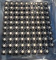
Frontside view of a sheet of WS281 LEDs.
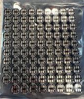
Backside view of a sheet of WS281 LEDs.
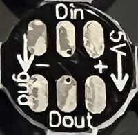
Closeup of wiring side of WS281 LED.
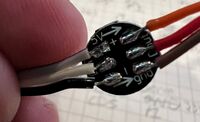
Backside wiring of WS281 LED showing power and signal in on the left and daisy chaining to next LED on the right.
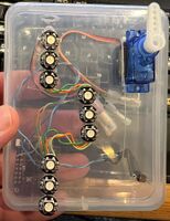
Prototype test box shows how multiple WS281 LEDs can be daisy chained together. In this case there are 3 signal heads, each with 3 LEDs.
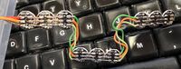
Photo showing how nine WS281 LEDs are "daisy chained" together to form three signal heads with three LEDs each.


- Pin +5V In
- Wire color: Grey
- Function: Input +5 volts to power this LED and all downstream LEDs on the chain
- Pin GND In
- Wire color: Black
- Function: Ground return for +5 volts and signal
- Pin DIn
- Wire color: White
- Function: Data Input signal, controls function of the LED
- Pin +5v Out
- Wire color: Grey
- Function: Output +5 volts to power downstream LEDs in the chain
- Pin GND Out
- Wire color: Black
- Function: Output ground return for +5 volts and signal for downstream LEDs
- Pin DOut
- Wire color: White
- Function: Output data signal, controls function of downstream LEDs
- Power: 30 watts
- Part number: ALITOVE WS2812B
- Source: Amazon.com
Servo

A miniature R/C servo provides power to move the semaphore flag into its three positions. Be sure to use the higher quality Miuzei brand or equivalent, as they have metal gears. The cheaper units have plastic gears and may not last in the rugged conditions of a railroad.
- Pin GND
- Wire color: Black
- Function: Return path for +5 volts and signal
- Pin +5V
- Wire color: Red
- Function: +5 volts power supply
- Pin Signal
- Wire color: Orange
- Function: Pulse Width Modulation (PWM) control signal
- Part number: Miuzei MG90S 9G
- Source: Amazon.com