Turbine Generator
1 inch scale
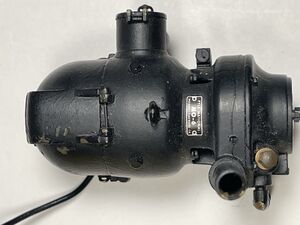
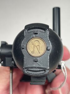
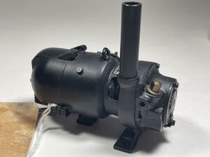
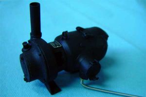
Moseley 1-inch scale turbo generator
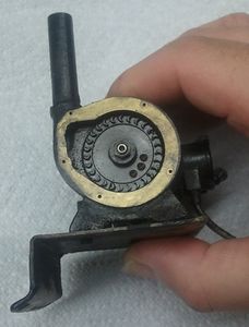
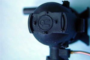
Moseley Generator showing the internal turbine blades. Photo by Karl Kobel.


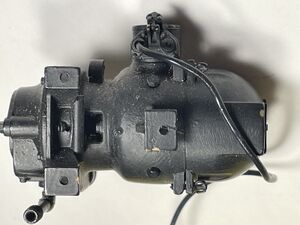
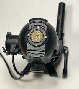
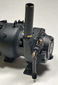
1.5 inch scale
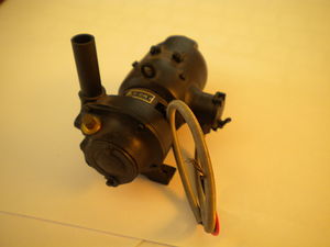
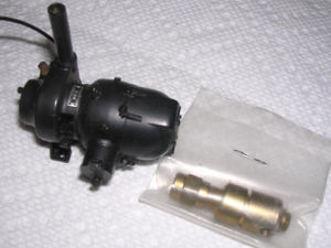
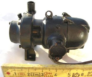
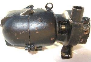
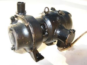
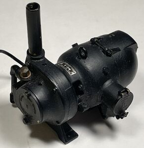
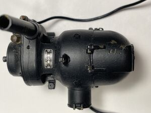
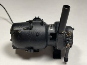
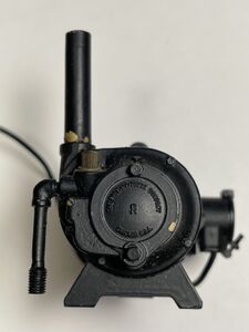
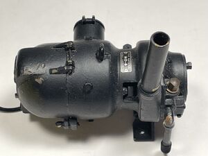
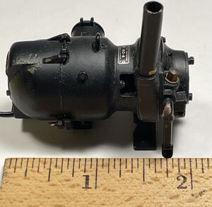
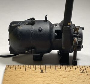
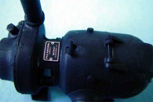
Turbo Generator(1.5 inch scale) by Francis Moseley.
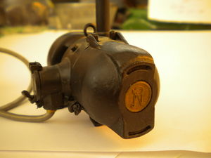
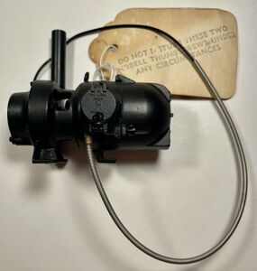
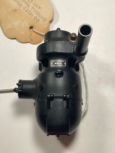
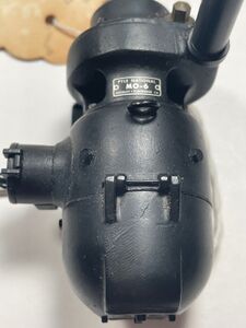
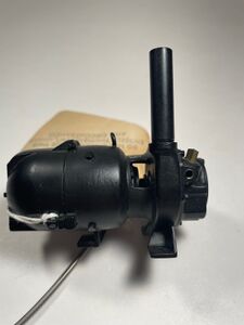
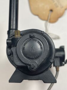
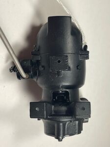
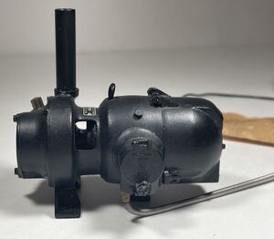
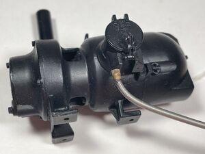
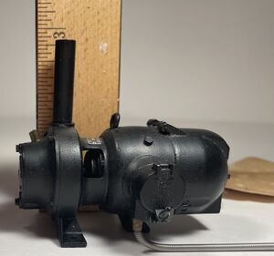
Moseley 1.5 inch Turbine Generator manufactured by Riding Railkits Inc


RichD posted the following Chaski.org, 21 March 2013:
- I'm very familiar with the Moseley Dyno. It is an alternator (AC) only. No brushes.
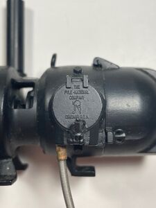
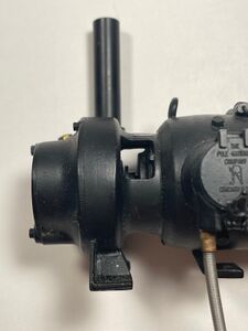
- Are you sure it's a Moseley? There should be a small lablel (F Moseley) and the top case "hinge" lugs will have a wire pin thru. The turbine rotor shaft will have a hex nut retaining the wheel.
- If it has ever had steam on it, chances are the stator is rusted thereby jamming the rotor. Also, if it was ever run too fast the magnet(s) may have exploded thus jamming it.
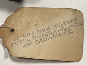
- Loosen the 2 turbine end screws and rotate the cover to the side. Reach in and flip the turbine wheel to see if it will turn. If it freely rotates, mechanically it is ok.
- With a multimeter, check the continuity between case and lead. Should be only a could of ohms. If there is no difference between shorting the meter leads and the dyno test, there's internal damage. IF ok, connect a 3V (PR-2) lamp load to the case and wire lead. Hook up air pressure and slowly increase pressure watching for the lamp to glow. It should be possible to get full brightness (2.4VAC). Be careful. If the lamp comes loose or burns out, the rotor will overspeed.
- If all of the above checks out you are good to go. If not, Plan B.
- Remove the 2 case screws and the wire "hinge" pin. Pull and twist with the fingers to try to separate the 2 halves. You may have to use a pair of knife blades to gently pry apart. What is holding it is the end shaft bearing is locktited in place. The stator (with wire coils) will stay in the turbine end. There are no wire connections on this end. All should appear nice and clean. Remove the turbine case screws and remove the casing. Hold the turbine wheel with fingers and remove the 3/16 AF hex nut. Slide out the rotor. The bearing may come with it. Also look out for an o-ring. If no mechanical damage is seen, try the meter test again. Sometimes a wire comes in contact with the case and the insulating coating is rubbed off shorting out the coil. Look for any bare copper spots around the stator. If you see a likely spot, press the wire to compact the coil so it won't contact the case. If still tests shorted (or very unlikely open) the stator now has to come out.
- Look around the outside bottom of the gen case in the gap area for a telltale bump in the paint or sand off the paint to find spot of soft solder. This is where the opposite end of the stator coil is joined to the case. There are two ways to attack this. Try to dig out the solder enough to allow the stator to slide out or just pry or pull till the wire breaks. It will have to be replaced (easy) anyway. Be careful with the lead and feed it thru the junction box hole as you go. Once the stator is out be looking for rub spots on the wires. If the coil is found to be testing good now and no mechanical damage is seen, reassemble. The grounding wire is soldered to the stator in a groove. Dig this out with a sharp blade. Replace with a longer bare wire, soldering into the groove. Slide the case over the stator feeding the wire thru the hole until you are sure the stator is seated on the shoulder. Test for shorted coil again. Try the end case on and test again. If all seems ok, reassemble all and solder the ground wire. You should be good to go.
- Final notes. There must be a slit washer on the shaft between the turbine and gen case. This is an attempt to avoid the condensate blowing out of the turbine case and into the gen case and bearing causing rust. I have earlier posts about this and the fix.
- With normal operation, the dyno should produce enough current to fully illuminate a PR-2 flashlight lamp. That is 2.4V (never 3V) at 1/2 Amp.
- Good luck.
Design Principles
There are lots of ways to find an end to a problem, but don't overlook K.I.S.S. ! Think about the entire system and how it works, what is available for input and most of all, what you want out of it. I have built enough miniature "dynamos" to find that simple is as simple does.
- 1.5" scale units must have small turbine wheels and the resulting need for high speeds.
- A rotor built with speed in mind has no problem with 100K + RPM should it occur.
- Steam issuing from a nozzle has a limited velocity and the blades will likely not attain 50% of that especially when driving a load. Always keep a load ON.
- Control the steam feed with small pipe. 1/8" copper tube is plenty. Flow is controlled by the nozzle aperture. For best velocity use a venturi. Convergent-divergent tapers.
- Don't forget the boiler operating range. Still having lights at 60 psi would be nice. So, having a wide range of output voltage followed by an electronic regulator is similar to the locomotive boiler. Reserve pressure is useful when needed.
- Spinning magnets in a wound field makes an alternator (think automotive). Full wave rectify the output in the unit and ground the minus lead. Now one hot lead is all you need. Less mess. The loco chassis is ground (circuit return). Use Teflon #20 lamp leads.
- A simple 3 terminal regulator chip (LM317 from Radio Shack) is adjustable and self limiting for over temp and current. It shuts down in case of a fault. Use as many as needed for different circuits/lamps. See the spec sheet for limitations (operating area).
- Use low voltage lamps (large selection of 3V types - or LEDs) to avoid the need for large numbers of turns in the field thus allowing large dia wire to keep the internal resistance as low as possible. Resistance eats amps. #22 or 20 works well.
- The schematic attached is as simple as it gets. Don't forget a heat sink.
- The dyno can attain nearly 400° F in operation sitting on top of a boiler. Internal electronics have to be pretty tough to servive and work as well. Ventilation is a must.
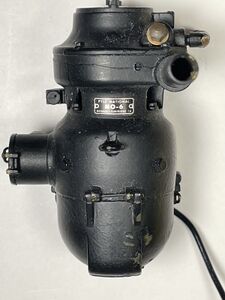
By the way, the MO-6 Pyle National Dyno has 3 speed control systems built in. Centrifugal governor steam valve, over-speed brake and an eddy current drag disc for over-current. Can't fit all that in a miniature. Shaft rotates CCW. 3450 RPM. 32V. There are also 4 nozzles. Two primary and two secondary.
RichD toolman8(at)copper(dot)net

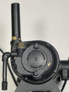
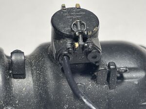
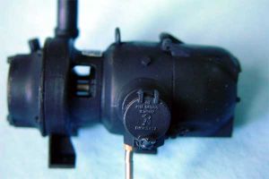
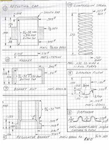
Pressure Regulator
Rich Carlstedt provided drawings for the Moseley pressure regulator:
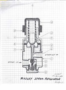
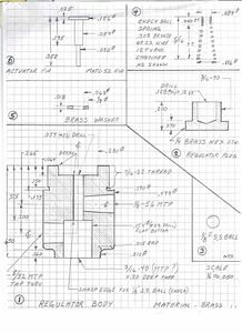
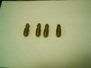
Original Mosley turbo generator regulators. Photo by David Sclavi


References
Don Carr posted the following in Chaski.org, December 2003:
- Here is a listing of construction articles and notes (both published and unpublished) on miniature working turbo-generators for live steam locomotives. I am going from the earliest material which I have to the more recent.
- 1. The Miniature Locomotive, September - October (part 1), November - December(part 2) 1952, "3/4 Inch Scale Steam Turbo-Generator" by R. E. Thompson. Refers to a design originally developed by Otha Hege of Lexington N.C.
- 2. Model Engineer, November 11, 1954 (part 1) and November 18, 1954 (part 2), "Miniature Steam Turbo-Generators" by E. Rowbottom (South Africa). This turbo-generator is for a 5 inch gauge locomotive.
- 3. Model Engineer, March 10, 1955, "A Miniature Turbo-Generator" by R. E. Thompson (U.S.A.) Basically, this is a technical summary of The Miniature Locomotive articles.
- 4. A blueprint sized 18 inch by 30 inch dated July 21/71, DWG C-5005 drawn by WHD with note "Original design by O. Hege in 1951. Modified and clarified by WHD 1971". I am certain that this print is one that I purchased from W. H. (Bill) Dykeman of York Central Railway, Prince Edward Island, Canada. A very clear, interesting and informative blueprint.
- 5. Model Engineer, 17 January 1986, "A Steam Turbo-generator" by Terry Timms. Designed for a 5 inch gauge Sweet Pea locomotive.
- 6. Live Steam, "A Turbo Generator" by Richard Chiapparelli, September/October 1998 (part 1) and November/December 1998 (part 2). Originally for a 1 inch scale Atlantic but increased in size for a 1-1/2 inch scale locomotive.
- 7. Unpublished notes taken in 1998 for a design and drawings (dated Feb 1983) by Ian Wynd of C.O.A.L.S (Central Ontario Association of Live Steamers) for a 3/4 inch modified and updated Hege/Thompson type turbo-generator. He made a number of these units and at one time some may have been sold through Miniature Power Products (Ted McJannett) but they are not available now. I have one photo showing the units disassembled and some of the tooling used in their construction.
External Links
- Photo of turbo generator for a Big Boy
- Moseley Generator Regulator
- "Steam Turbo Generator", Richard Chiapparelli, Live Steam Magazine, Part 1 September-October 1998, Part 2 November-December 1998
- "1.5" scale Live steam Mosley generator 1:8 scale", Shapeways
- "LS Mfg MO-6 Turbogenerator Castings", Chaski.org
- List of articles on Turbine Generators, Chaski.org
- "For Those of You Into Working Turbogenerators", Chaski.org
- "Moseley Generator", Chaski.org
- "Pyle National Turbo generator MO-6", Chaski.org
- "Steam turbine generator", Chaski.org
- "Handpiece Headquarters", source for dental instrument high-speed bearings
- "Steam Turbines, Part II", PDF